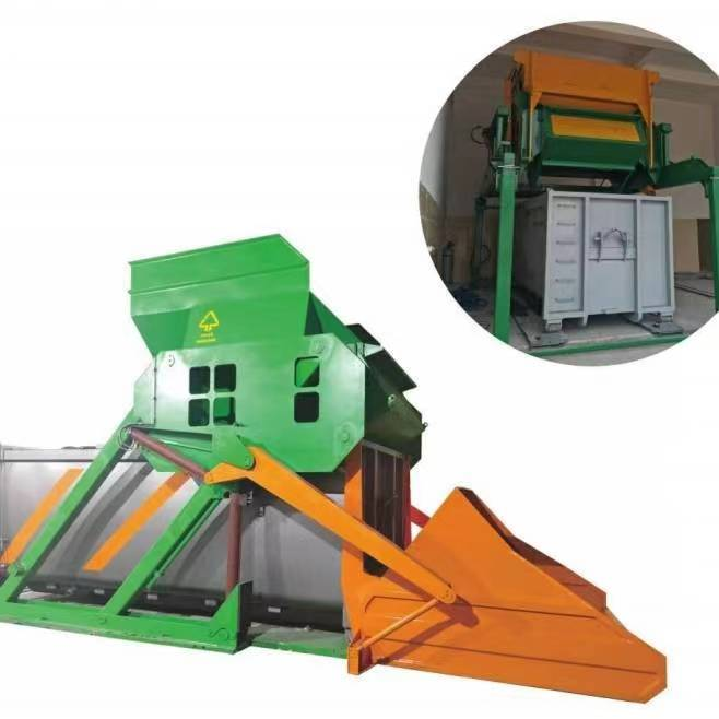
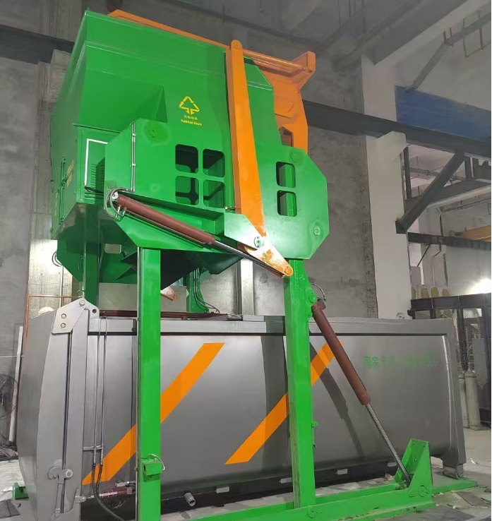
Industrial Garbage Compactor
The LM15YS/LM22YS Series Single-Unit, Single-Position Split-Type Industrial Garbage Compactor is a compact waste compaction and transfer system designed for small-scale operations. It is primarily suited for the collection and transfer of municipal solid waste in urban streets, large communities, schools, hospitals, and rural areas with daily processing capacities ranging from 20 to 100 tons, where space is limited and high environmental standards are required.
HD offers OEM&ODM service for industrial & commercial garbage compactor, please feel free to contact us!
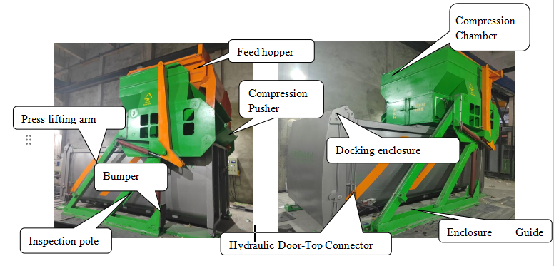
Product Composition
The industrial garbage compactor consists of a 15m³ LM15X docking container or a 22m³ LM22X docking container, forming a waste collection and transportation system.
| Number | Compressor | Daily processing capacity per unit | Trash Can Model/Capacity | Matching transfer vehicles |
| 1 | LM15YS | 20-60 ton | LM15X/15m³ | 5180ZXX |
| 2 | LM22YS | 30-100 ton | LM22X/22m³ | 5250ZXX/5310ZXX |
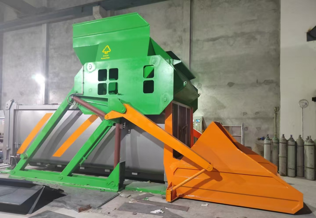
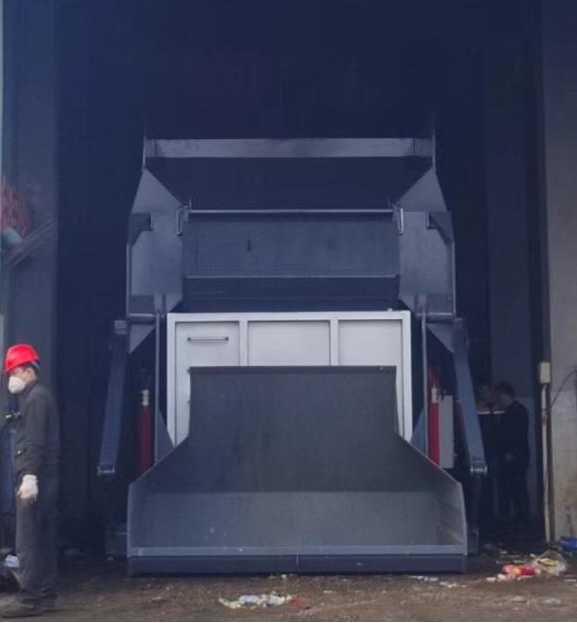
Primary Mode/Structure of Industrial Garbage Compactor
One-machine-one-position model
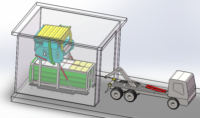
First, empty the waste bins into the empty bay. The mobile compactor rotates to the bay containing the empty bin, automatically interlocking. Loose household waste collected by the front-end collection vehicle is then tipped directly into the elevated compression chamber via the tipping mechanism. The waste is compressed and reduced in volume by the elevated compression mechanism directly into the bin. After completing waste compaction at this bay, the compactor moves to the adjacent bay. Finally, the waste-filled bin is transported via a hooklift truck.
Primary Advantages of the Industrial Garbage Compactor
HD industrial garbage compactor station has the following advantages:
- Unloading is easier and safer: This system removes the problems of residue entrapment and sewage leakage during front-end unloading while the ram head is kept outside the container to avoid corrosion and secondary pollution.
- Efficient and space-saving structural design: Their overlapping compactor-container layout maximizes site space. The slanted and top-loading structure compaction is more efficient, while less energy is used. It is ideal for consolidating both household and food waste.
- Reliable performance in the toughest of conditions: This design prevents freezing-related underloading in the winter months, common in the North. It also enables container hooking at tight sites and further reduces energy consumption for the same loading capacity that older designs used.
- Convenient and safe maintenance: With the ram head and compression chamber always exposed, maintenance and cylinder replacement are kept simple. The hydraulic power system has been situated to allow the user ample working space, which is meant to improve the safety and accessibility of the service.
Technical Specifications
| Items | Performance Parameters | |
| LM15YS | LM22YS | |
| Matching Bin Capacity (m³) | 15 | 22-24 |
| Matching Transfer Vehicle Specifications | 5180ZXX | 5250ZXX/5310ZXX |
| Theoretical Hourly Output (Single Unit) (t/h) | 10 | |
| Hopper Feed Width mm | 2730 | |
| Maximum Compaction Force (kN) | 300 | |
| Compaction Cycle Time (s) | 40 | |
| Tipping Bin Volume (m³) | 6(Non-Sinking Hopper Mode) | |
| Maximum Lifting Capacity of Tipping Bin (t) | 2 | |
| Post-Compaction Waste Density (kg/m³) | 700-750 | |
| Pump Station Power (kW) | 11 | |
| Compaction Method | Cross-cylinder plunger compression | |
| Compactor Lifting Method | Parallelogram Swing Lift | |
| Compactor Horizontal Tilt Angle | 30° | |
Product Features
(1) Reduced Civil Engineering Requirements
1) Same-side collection and transfer. Both collection and transfer vehicles connect to the compactor on the loading side, sharing the same operation and transfer platform. This significantly reduces site footprint and lowers civil engineering costs.
2) Elevated Feed Compaction. The equipment employs elevated feed compaction, with the compaction mechanism positioned atop the waste container. It interfaces vertically with the container, utilising a rammer and slide plate to compact waste during operation, resulting in a compact footprint.
(2) High Adaptability
1) Large hopper capacity. With a geometric volume of 4-6m³, the hopper can hold over 2 tons of net waste per load. This accommodates both single-load unloading from small motorised collection vehicles and hook-arm trucks with a total payload capacity of 3 tons.
2) No pit required. Minimal site preparation needed—no excavation required.
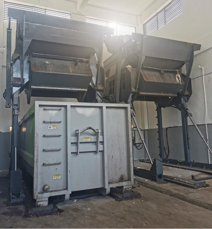
(3) Cost-Efficiency
1) One machine, multiple bins: The compressor uses a detachable design, enabling a single unit to compress multiple bins across different locations. This significantly boosts operational efficiency and cost-effectiveness.
2) Separate unit and transport: The integrated compression and separate transport structure allows the compressor and waste bin to operate as one unit during compression while separating for transport. Waste bins are transported independently with vehicles. Compared to integrated compression systems, this reduces bin weight, effectively increasing waste loading capacity without exceeding transport limits and lowering transportation costs.
(4) Environmental Protection and Energy Efficiency
1) No waste spillage. A sealed cover is installed above the compression mechanism, featuring a three-sided sealing structure. When the hopper dumps waste, the three-sided seal effectively prevents scattering and spillage, ensuring excellent environmental performance at the station.
2) No wastewater dripping or discharge. The equipment employs high-position compression, with the compression mechanism positioned above the waste bin. This design exerts less pressure on the bin door compared to low-position compression mechanisms and avoids direct contact with wastewater, reducing the risk of dripping during compression. Wastewater is stored within the bin and transported away with the collection vehicle, ensuring no wastewater discharge throughout the entire compression and transfer process, delivering excellent environmental performance.
3) Quiet operation with energy efficiency. The hydraulic system employs a dual-pump silent drive, enabling multi-stage speed regulation. This ensures smooth operation, low noise levels, reduced oil temperature, and significant energy savings.
(5) Easy Maintenance
External maintenance design ensures safety and convenience. The compression mechanism is positioned above the waste bin, with all components except the pusher head remaining completely isolated from waste throughout the entire process. This significantly improves the operating environment for hydraulic cylinders and other parts, extending their service life. Additionally, the external placement of the hydraulic cylinders facilitates maintenance and repairs.
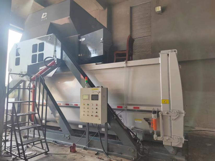
(6) Safe and Reliable
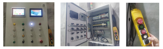
High safety standards. A bucket burst valve is installed at the front end to prevent rapid bucket descent that could endanger personnel. The product features an alarm system that alerts operators to exercise caution during safety-critical operations. A standard wired control handle allows operators to manage the equipment from a safe distance, equipped with an emergency stop button to safeguard both personnel and machinery. Safety labels are affixed to the product to guide operators in safe operation.
Product Application Cases
1. Site selection: Most garbage stations are usually located near roads to ensure that collection vehicles can reach the site. Be careful to avoid sidewalks and lanes, and be vigilant to prevent vehicle rollovers or collisions.
2. Hardening, Embedded Parts, and Drainage Well Construction:
- Excavation Dimensions: Provided based on the user-specified equipment model and specifications. (Hardened surface shall be parallel to the road surface).
- After excavating the pit, continue digging the drainage well foundation pit on the wider side. Dimensions: Length 1500 mm, Width 1500 mm, Height 1800 mm. (For construction convenience, the two pits may be interconnected).
- Install drainage pipes connecting the pit bottom to the drainage well. Then pour a reinforced concrete foundation layer approximately 200 mm thick (ensuring level corners).
- After the concrete foundation layer has cured, erect formwork around the pit and drainage well walls and pour reinforced concrete to raise the walls to ground level.
- Maintain a minimum spacing of 1000 mm between the equipment pit and the drainage well. Backfill the surrounding area with soil, compacting it to a level surface. Place embedded parts into the pit. Ensure consistent gaps around the perimeter, and position embedded parts according to the specified dimensions on the drawings.
3. Position the embedded parts relative to the pit, then pour the concrete platform. Use the relative dimensions between the track and embedded parts as critical control dimensions during concrete pouring. The remaining surfaces may be sloped at approximately 5 degrees to facilitate drainage. Ensure seamless connection between the platform and roadway (Requirements: Track and embedded parts must use cement with a strength grade of C25 or higher, with a hardened thickness of no less than 300mm; the platform hardened thickness must be no less than 100mm).
4. If decorative tiles are to be affixed, lower the concrete platform foundation to allow clearance, ensuring the finished tile surface sits below the embedded parts’ upper surface.
6. During construction, promptly wipe away any cement slurry splashed onto embedded parts or track surfaces with a damp cloth to prevent hardening and stubborn stains.